Overview
Testing whether an embedded device could feel expressive.
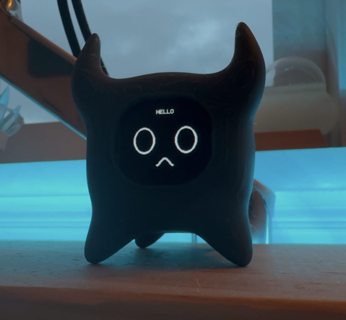
The project began with a simple question: could a small electronic object feel more like a desk character than a piece of hardware? Answering it required the visual design, enclosure, internal layout, animation and firmware to work as one product.
I owned the complete build. That made this an architecture exercise as much as a craft project: every decision at one layer affected the available space and behaviour at the others.
01 / Product intent
Start with personality, not components.
I developed the initial silhouette and expression studies in Procreate before committing to electronics or geometry. This established the visual target early and prevented the physical shell from becoming a generic box around a screen.
The companion needed to be compact, recognisable and serviceable enough to assemble after printing.
02 / Physical architecture
Design the inside before sculpting the outside.
I created a negative volume in Fusion 360 to represent the real dimensions of the microcontroller, display and supporting components. That volume became a hard constraint for the enclosure.
I then moved into NomadSculpt to build the organic exterior around the engineering model. This two-stage workflow kept the characterful form while protecting component clearance and fit.
03 / Software and motion
Use animation as the interface.
The ESP32 runs the on-device behaviour and display logic. I created the visual states in Aseprite, then prepared and loaded them for the embedded display.
With no conventional screen controls, movement and expression carry the interaction. Timing, legibility and animation changes therefore mattered as much as the firmware structure.
04 / Integration
Prove each layer, then assemble the system.
I tested the electronics before final assembly, checked the printed geometry against the components and brought the animation pipeline onto the ESP32. The final build houses the electronics cleanly and runs the custom visual system as intended.
The outcome combines the printed shell, assembled electronics, firmware and original animation assets.
05 / Lessons
Cross-disciplinary work is constraint management.
The most useful lesson was to treat mechanical, electrical and software decisions as one dependency graph. Accurate internal geometry reduced fabrication risk; early electronics testing reduced assembly risk; and designing animations for the actual display kept the concept grounded.
A next iteration would improve access for repairs, formalise firmware states and test additional expressions with users.